XEBEC Back Burr Cutter and Path™
XEBEC Back Burr Cutter and Path™
Spherical deburring cutter and custom-made tool path
An innovative CNC crosshole deburring solution, which, in combination with the spherical deburring cutter and the customized Path (NC data set), enables high-precision deburring of 3D-curved crossholes. The Path is created specifically for the customer application, enabling deburring without secondary burr formation at the same time, freeing you from having to make your own program.
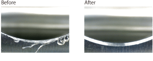
High quality
- Uniform edge shape thanks to an optinal tool path
- Inhibits secondary burrs by calculating optional cutting angles
Long tool life
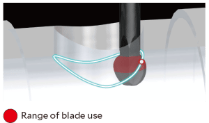
The continuous displacement of the contact point of the cutter during machining increases the tool life many times over compared to comparable tool solutions.
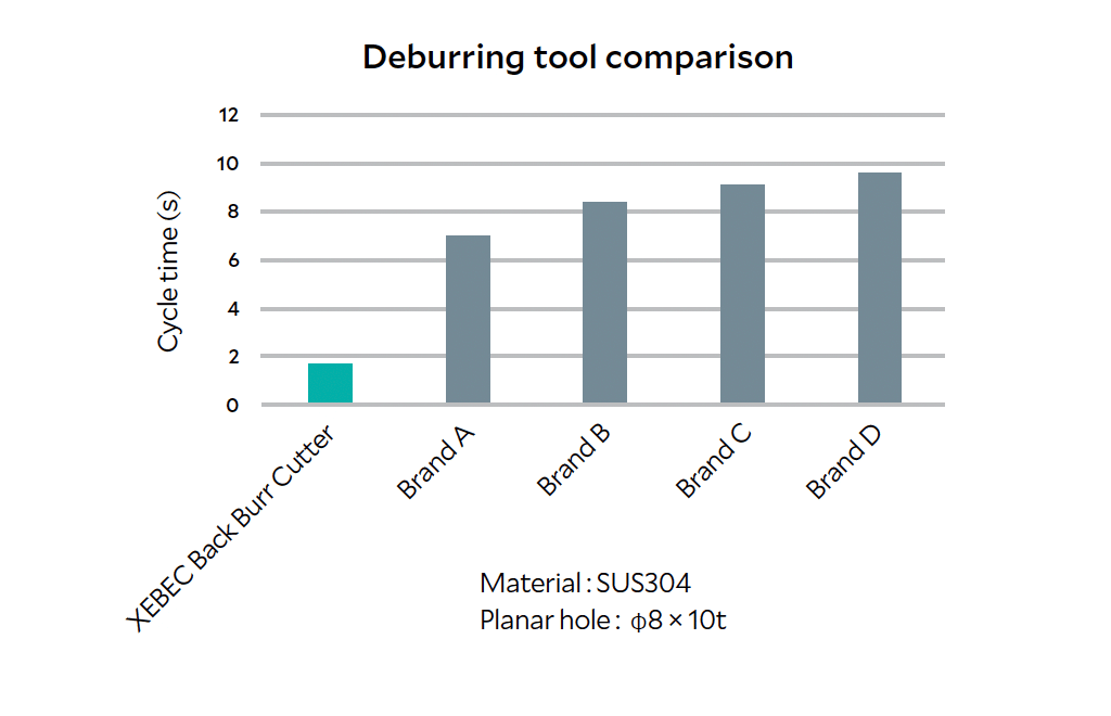
World’s fastest deburring
Cycle time is reduced because there is no wasted motion in the
cutter path. Cycle time is up 10 times faster than conventional
deburring tools.
Deburring tool comparison
XEBEC Back Burr Cutter and Path™
Optimal solution for high-precision deburring of 3D-curved crossholes
Applicable equipment
The tool can be mounted on machining center (XYZ-axis) or combined lathe (XZY or XZC-axis). 3-axis simultaneous control is required.

Machining center

Combined lathe

Special machine

Robot

General purpose lathe with milling function

Drilling machine

Rotary tool
(electric)

Rotary tool
(pneumatic)
Product component
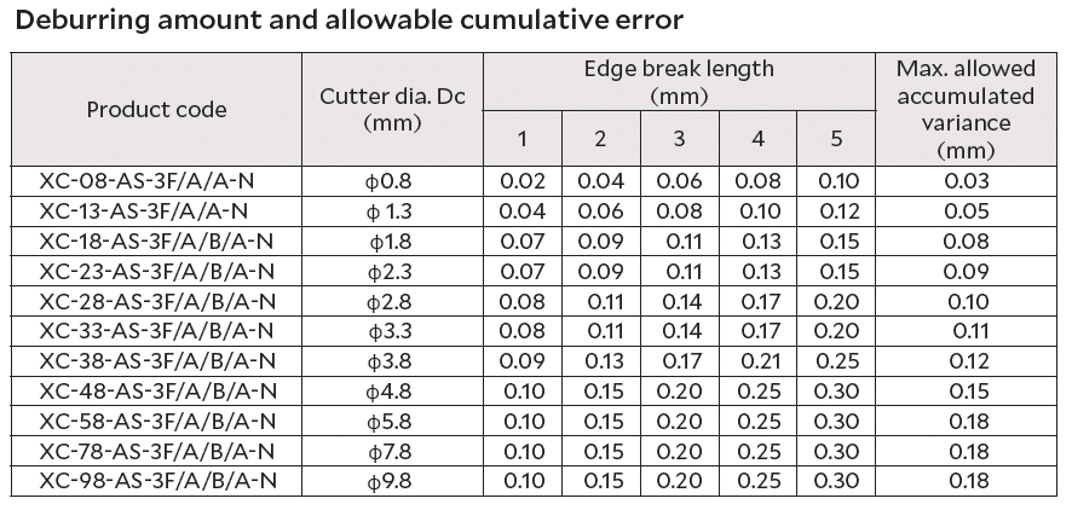
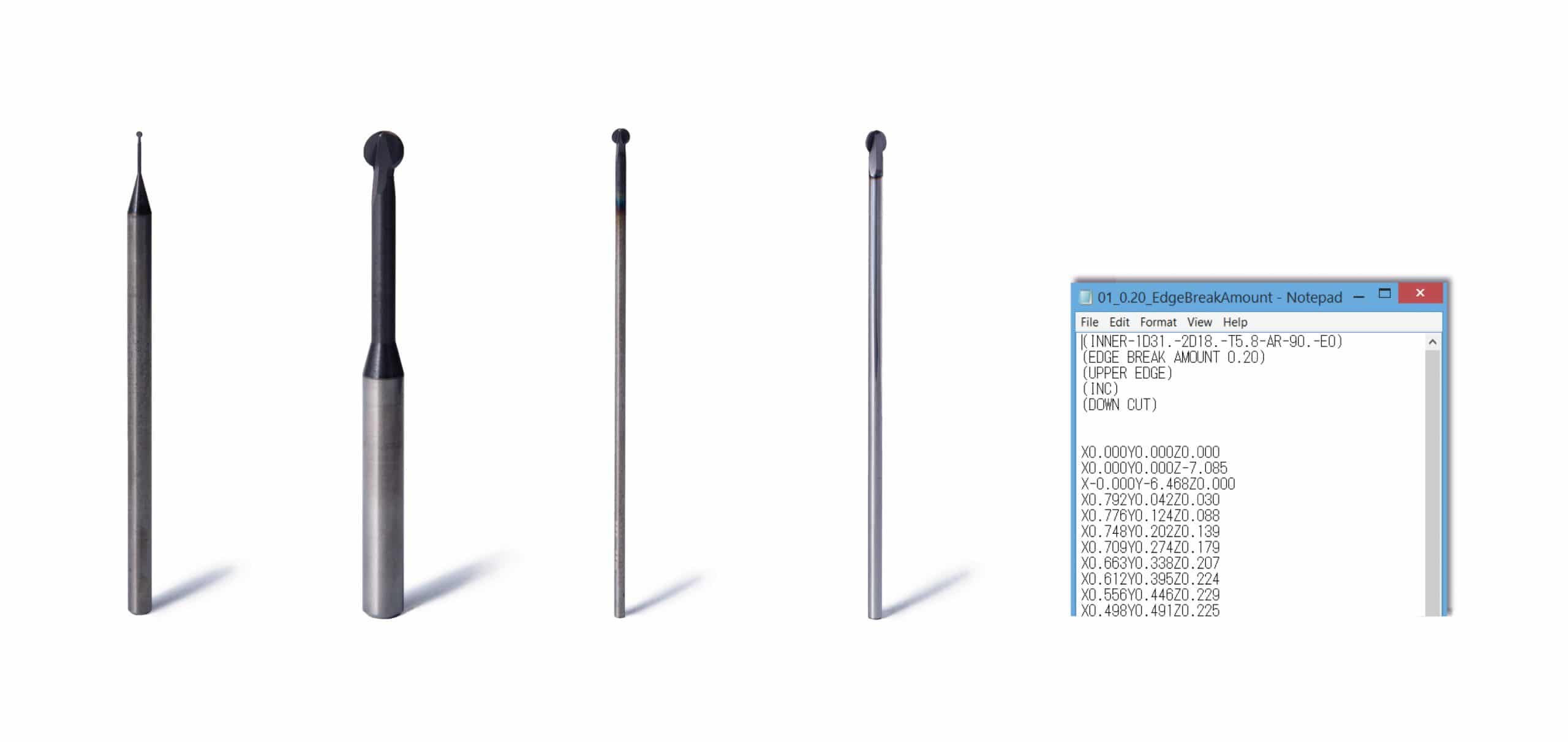
Spherical deburring cutter and Path (NC data set) created specifically for the customer application.
See online “hole-deburring application form” for more details on custom-made tool Path.


XEBEC Back Burr Cutter and Path™ For Machining Center
Instruction Manual Download For Combined Lathe
Applicable equipment
The tool can be mounted on machining center (XYZ-axis) or combined lathe (XZY or XZC-axis). 3-axis simultaneous control is required.
*For combined lathe, polar coordinate interpolation is required.
*It cannot be used manually.
How to order XEBEC Back Burr Cutter and Path

You can check whether XEBEC Back Burr Cutter and Path is applicable for your hole-burr problem and environment.
The result will be available soon.
Please access from the following link.
In case you have difficulties filling out sheets online
Please send us a completed “Back Burr Cutter and Path application sheet” if you have difficulties filling out the online form. We will select an optimal Cutter size, assess whether XEBEC Back Burr Cutter and Path is applicable to your workpiece and machining equipment, and provide XEBEC Path number.
There are 2 types of application sheet; for machining center and combined lathe.
Please download and fill out a sheet depending on your machining equipment.
Application sheet
Edge shape and dimensions after deburring
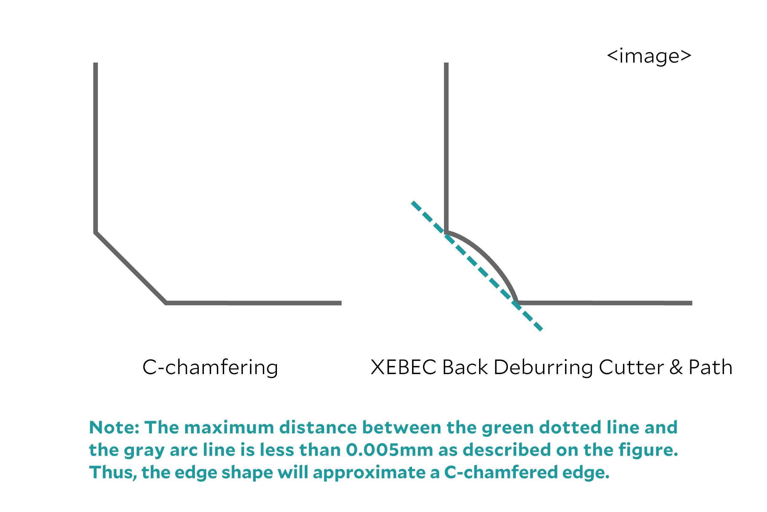
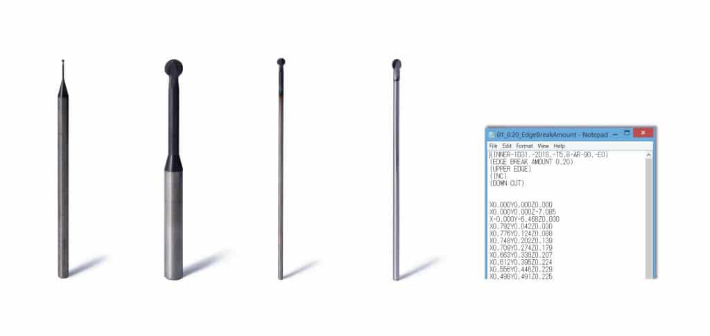
For the reason above, we consider “a width of an edge after deburring” as “deburring amount”

As a result of having pursued the effective shape for crosshole deburring, the Cutter is spherical.
It is not possible to chamfer or round-chamfer the edge.
The following shows the edge shape after deburring.
Processing conditions
First, please try under initial processing conditions instructed in the tool guide.
| Product code | Cutter diameter (mm) |
Projection amount | Aluminum alloy | Carbon steel/alloy steel/ stainless steel | ||
| Spindle speed (min⁻¹) |
Feed (mm/min) |
Spindle speed (min⁻¹) |
Feed (mm/min) |
|||
| XC-08-A | φ0.8 | 5D | 20000 | 650 | 20000 | 600 |
| XC-13-A | φ1.3 | 5D | 20000 | 650 | 20000 | 600 |
| XC-18-A | φ1.8 | 5D | 20000 | 650 | 20000 | 600 |
| XC-23-A | φ2.3 | 5D | 18000 | 950 | 15000 | 750 |
| XC-28-A | φ2.8 | 5D | 15000 | 1400 | 12500 | 1000 |
| XC-33-A | φ3.3 | 5D | 12700 | 1250 | 10600 | 1050 |
| XC-38-A | φ3.8 | 5D | 11000 | 1600 | 9200 | 1200 |
| XC-48-A | φ4.8 | 5D | 8500 | 1100 | 7200 | 1100 |
| XC-58-A | φ5.8 | 5D | 7000 | 1600 | 4500 | 1350 |
| XC-78-A | φ7.8 | 5D | 5400 | 1350 | 4500 | 1350 |
| XC-98-A | φ9.8 | 5D | 4300 | 1300 | 3600 | 1100 |
| XC-18-B | φ1.8 | 10D | 4400 | 220 | 4400 | 220 |
| XC-23-B | φ2.3 | 10D | 3500 | 220 | 3500 | 220 |
| XC-28-B | φ2.8 | 10D | 2800 | 220 | 2800 | 220 |
| XC-33-B | φ3.3 | 10D | 2400 | 190 | 2400 | 190 |
| XC-38-B | φ3.8 | 10D | 2000 | 160 | 2000 | 160 |
| XC-48-B | φ4.8 | 10D | 1600 | 120 | 1600 | 120 |
| XC-58-B | φ5.8 | 10D | 1300 | 100 | 1300 | 100 |
| XC-78-B | φ7.8 | 10D | 650 | 70 | 650 | 70 |
| XC-98-B | φ9.8 | 10D | 500 | 50 | 500 | 50 |
How to install
Paths are made by XEBEC Technology and delivered to a customer via email.
Therefore, you only need to install the Path, set a starting point of the Cutter, and set processing conditions. You do not need to program on your own.
Please refer to the tool guide to see how to set a tool length offset and a starting point.
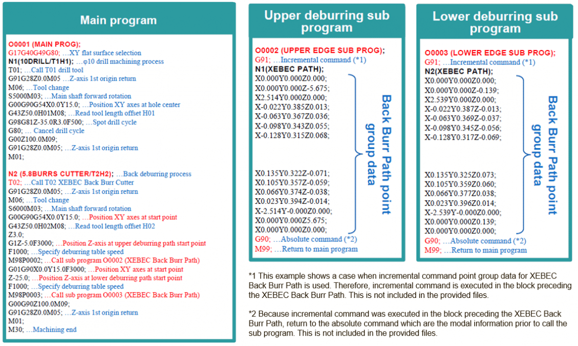
The following explains how to install incremental command point group data for XEBEC Back Burr Cutter and Path™
(for machining center, B-type hole) on a processing program.
*Control system is set in accordance to FANUC. Please adjust G codes in the program according to your own system.
Program overview
